Customer Portal
The R2Sonic Saturation Monitor that is available in Sonic Control (Status > Saturation Monitor) was initially developed to assist in backscatter surveys.
The Saturation Monitor graphs the degree of receiver saturation; reflecting the intensity of the received acoustic energy. The Saturation Monitor (SatMon) provides the surveyor with a graphic presentation to maintain a consistent intensity level during the backscatter survey. The SatMon has now become an essential tool for traditional bathymetry surveys as well, giving the surveyor an immediate indicator of the effect of changing operating parameters.
Jonathan Beaudoin (at the time with the Center for Coastal and Ocean Mapping at the University of New Hampshire and now Managing Director at QPS B.V.) developed the SatMon in 2013/2014. The first instance of the SatMon was in the 27 June 2014 release version of Sonic Control.
Opening the Saturation Monitor for the first time will automatically enable the intensity output in Sonar Settings. Closing the SatMon window will not disable the intensity output.
How the Saturation Monitor works
The Saturation Monitor uses the range, intensity, and TVG parameters for each beam (from the BTH0 datagram) to compute a logarithmic intensity level. The saturation point is then calculated based on proprietary parameters for R2Sonic multibeam echosounders. Then, how close the beam echo level is to the saturation point, as a percentage, is computed and plotted.
Power, pulse width, gain, absorption, and spreading loss influences the beam intensity. A change in value, in any of the parameters, will change the intensity, and this will be reflected in the SatMon. Outside of the sonar, the seafloor absorption and water column conditions will also be an influence on the beam intensity, and, again, a change in these environmental conditions will create a change in the SatMon graphics.
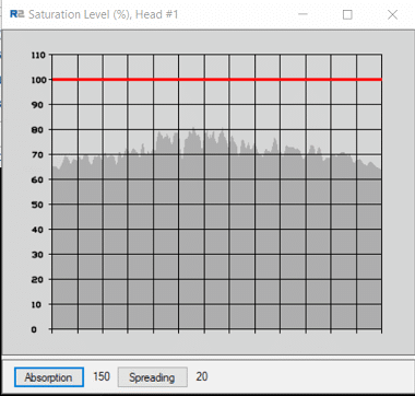
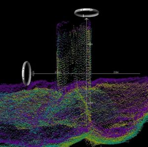
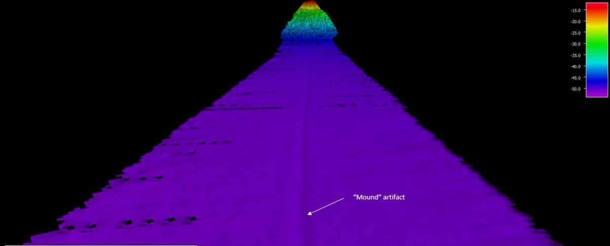
The red line, at 100, indicates 100% saturation of the receivers; the receivers will no longer operate linearly at this level of saturation. In fact, the receivers can be oversaturated at levels just under 100% as well. When the receivers are operating in a non-linear manner, the bottom detections in the nadir region will be very erratic, and there will be a noticeable nadir track or artefact in the data.
When the receivers are in a saturated condition, observing the nadir bottom detections, in Sonic Control, will show the nadir bottom detections moving erratically, unable to portray the real bottom.
Example of an oversaturated receiver and how it impacted the survey
Below, is an image from a customer, sent to R2support, because of a nadir artefact; illustrating one manifestation of the nadir artefact caused by the nadir receivers being in saturation.
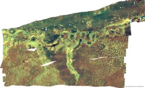
With backscatter, when the receivers are non-linear, it will disrupt the angular array analysis (ARA) in Geocoder because the ARA compares the intensity as part of the bottom type computation (along with the angle from nadir). When the receivers are non-linear, the nadir intensities are no longer valid.
Looking at the angular response curve, which plots the ARA, there is no peak as there should be because of the non-linear state of the nadir receivers. Usually, the available correction tools will not be able to correct the data. The data will be not able to be post-processed.
Best practices
The intensities, as seen in the SatMon, will form a peak at nadir; falling off towards the outer beams.
- Increasing Power will tend to increase the peak at nadir, with little influence in the outer limits of the swath
- Increasing the Pulse Width will tend to increase the intensity level in the outer beams
- Changing Gain will tend to move all intensities up and down
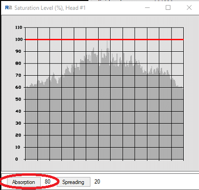
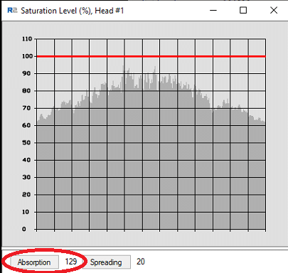
In the Saturation Monitor, there are controls to adjust the Absorption and Spreading Loss; these are two of the main variables in the Time Variable Gain (TVG) calculation.
- Absorption is frequency, temperature, and salinity dependent
- Spreading Loss increases with depth, but is not influenced by the same factors as absorption.
Because the TVG values are integral to the saturation calculation, the ability to adjust the parameters are included in the SatMon.
Below is an example of the effect of a change in absorption makes in the intensities. This change would not be seen in bathymetry data, but it would be very noticeable in backscatter data because it should be evident that the correct absorption value makes the intensities more consistent across the swath.
R2Sonic recommends:
- Keeping the Saturation Monitor visible at all times for all types of survey as it is the primary visual aid to assist in tuning the sonar
- Targeting a saturation of 60% to 80%, depending on bottom composition
- Be aware that very shallow and very deep survey are special conditions where the saturation limits may have to be ignored
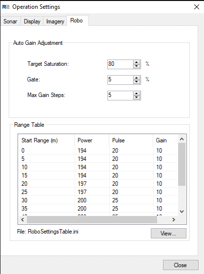
ROBO™ mode and the Saturation Monitor
The R2Sonic ROBO™ mode uses the computed saturation percentage to set the Gain automatically (Power and Pulse Width come from a look-up-table based on the Range setting). The Target Saturation is, by default, set to 80%. The user can set their own target for average saturation. Under most conditions, the target does not require changing. The Gate is set to allow saturation fluctuations before a change in gain is made; this default value is ±5%.
In the ROBO™ window, the Range Table shows the Power and Pulse (width) defaults by Range setting, but note that all Gain values are set to 10; this is because the Target Saturation determines the Gain, and the 10 is merely a place holder.