Customer Portal
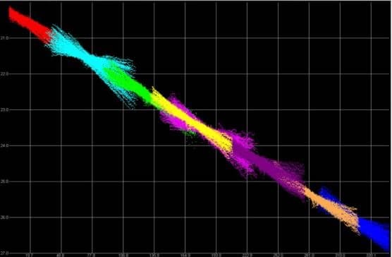
It’s unavoidable; Surveys are influenced and impacted by uncontrollable events – which is why keeping control over what you can is key for optimal data quality
Every surveyor has had a project affected by factors beyond their control. From poor weather to seafloor composition and morphology, fish activity, vessel traffic and more; uncontrollable factors will always affect surveys – which is why maintaining control over controllable factors is so critical.
Always ensure equipment is installed correctly
Prior to any survey, you should always perform a few basic checks on your installation, including:
- Motion sensor checks. The motion sensor should be aligned with the vessel’s axes to prevent roll/pitch bleed over, and must have an adequate data update rate.
- Gyrocompass checks. Ensure correct calibration and alignment with the alongship axis of the vessel.
- GPS antenna checks. The GPS requires a clear line of sight, waterproof connections and cable integrity. Whenever possible, use Pulse Per Second (PPS) time synchronization and NMEA ZDA/UTC time tags.
- Pole and rope checks. The pole must be secure, with no vibration. Ropes, fore and aft to secure the pole, should be avoided, unless they are above the waterline of the pole.
Obtain correct offset measurements
Always obtain correct offset measurements before you begin a survey. To do this:
- Measure offsets from the vessel reference point to the sensor’s reference point, then
- Measure from the sensor’s reference point back to the vessel reference point
These two measurements should match within a few centimeters or less.
Remember that when doing the vertical measurements using a plumb bob, that vessel list is taken into account.
Check and re-check offset measurements: it will save you time later on.
Perform multiple patch tests
- Always do multiple patch test data collections to ensure accurate results
- For pitch, latency and heading, try to use a feature rather than a slope
- If using a slope, the vessel steering must be exact, for both runs
- Wrecks, pipelines or other features are better suited for patch tests
- Pitch, latency and heading tests should be done in as deep water as possible
- Make sure to have a good, full water column sound velocity profile
Obtain accurate sound velocity
- If the sound velocity, at the head, is not measured correctly, the data may tend to curve either upwards or downwards toward swath limits
- Take multiple full water depth sound velocity profiles, ensuring you have a good and current profile for data collection
Dealing with error correction
Still encountered a survey error? Here are some examples of the most common artefacts:
- Heave artefact
- Characterized by uniform undulation or ridges across the entire swath
- Typical causes are:
- Motion sensor heave bandwidth setting
- Motion sensor offsets in error
- Motion sensor located in the wrong area
- Timing errors
- Motion sensor heave bandwidth setting
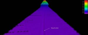
- Roll artefact
- Characterized by “Peak & Trough” outer swath oscillation and unaffected near nadir depths
- Typical causes are:
- Timing errors
- Misalignment of motion sensor with respect to vessel axes
- Sonar pole movement
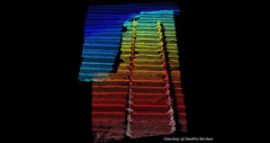
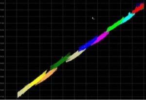
Example of high frequency roll artefact due to pole vibration Bow tie effect due to timing inaccuracy
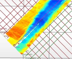
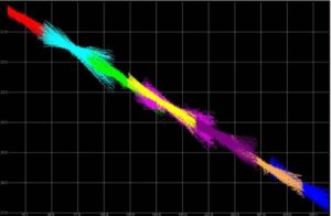
Typical display of pole wobble
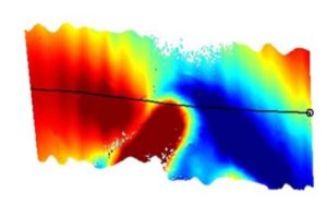
- Heave induced depth error
- Typical causes:
- Heave settlement at start of survey line after a turn
- Squat & Settlement
- Heave bandwidth setting
- Typical causes:
Fortunately, some errors can be corrected after the fact by making the necessary data adjustments. These include:
- Sensor offset measurement
- Perform a bar check to verify sonar Z offset
- Multibeam calibration values
- Re-do patch test data collection to get more data
- Tidal corrections
- Sound velocity
- Vessel squat and settlement
However, other issues, i.e. variable error effects, are not fixable after the fact. These include:
- Sound velocity errors with the SV sensor, on the sonar head, which is used for receive beam steering or if the fixed SV entered is inaccurate
- Sonar pole/mount/motion sensor movement
- Lack of suitable SV profile(s) of water column
- Variable positioning error (i.e. DGPS Correction Intermittency)
- Timing inaccuracy
- Motion sensor (heave/pitch/roll) drift – sensor failure
Every survey will present its own uncontrollable issues – poor weather, strong winds, rough seas. Yet it is possible to minimize errors and artefacts – and ensure the best data quality possible – by taking control over all the survey elements that you can, completing the necessary checks, tests and ensuring a robust, secure setup.