Customer Portal
Many support requests from clients using the Applanix POS MV (either stand-alone or I2NS) have shared the common issue of motion artefacts. However, it is simple to overcome these issues and others, by ensuring that your installation is correct and optimized. Below are our top tips for perfecting your setup.
POS MV setup tips (overview)
- Ensure that the POS is installed correctly and the settings are as prescribed in Applanix and R2Sonic manuals. By going through the manual step-by-step, you lay the optimal foundation for good data collection
- Ensure that the installation is optimized by always using the recommended location for the POS reference point
More detail on the required setup, settings and calibration is below.
Important settings and benchmarks
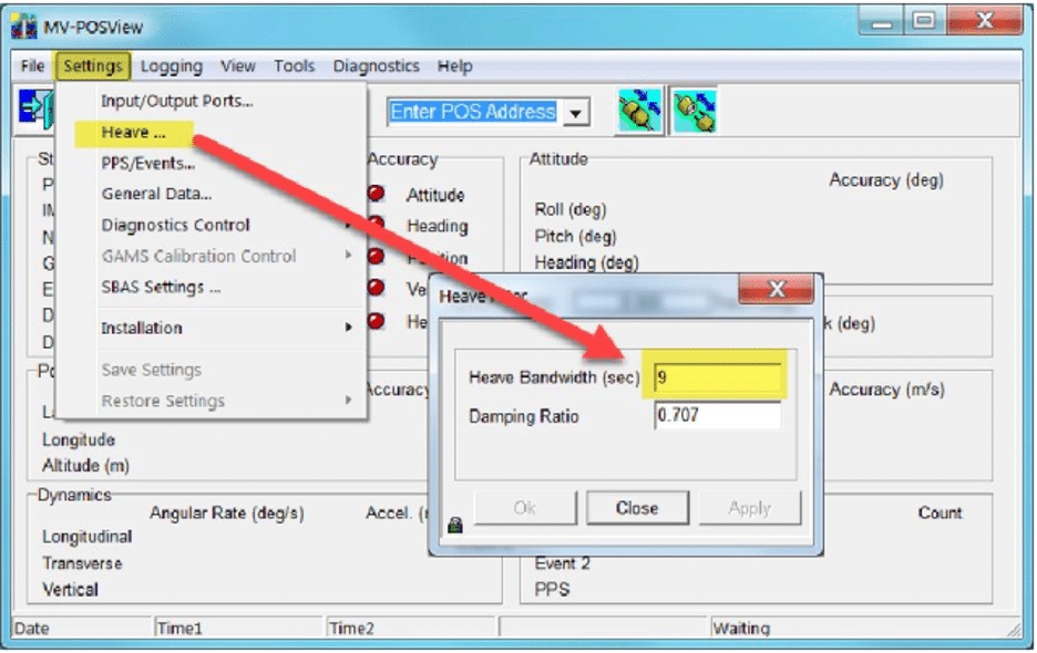
Heave Settings
- Use 9 seconds heave as a default setting
- Use 12 seconds in ocean swell, unless the period is longer
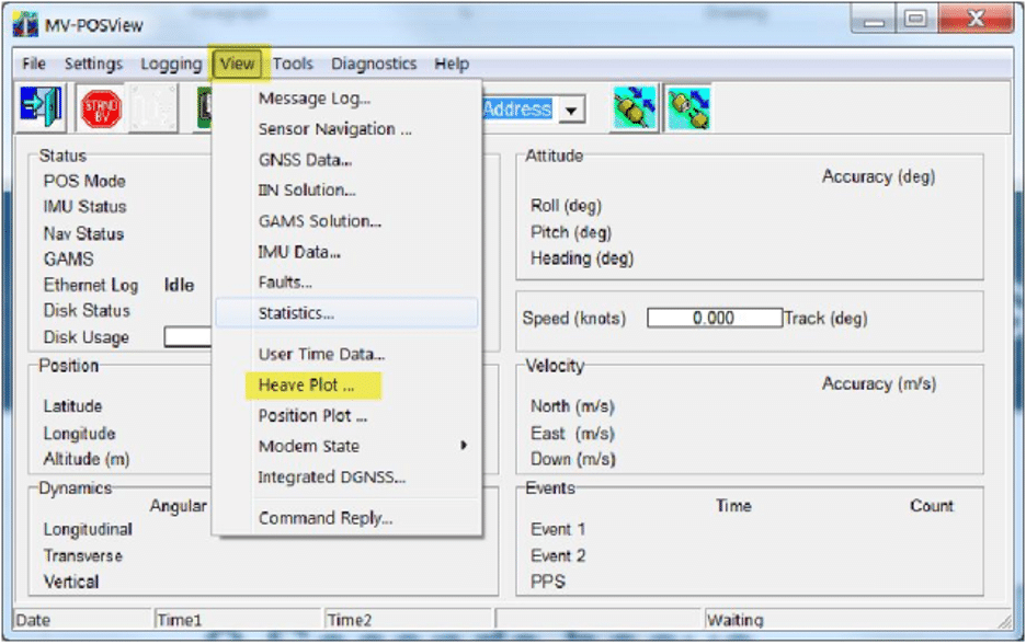
- Viewing the heave plot in POSView is a good way to confirm the actual heave period, aiding correct calibration
PPS Settings
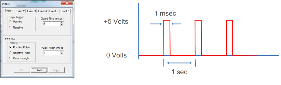
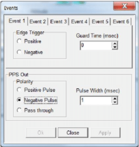
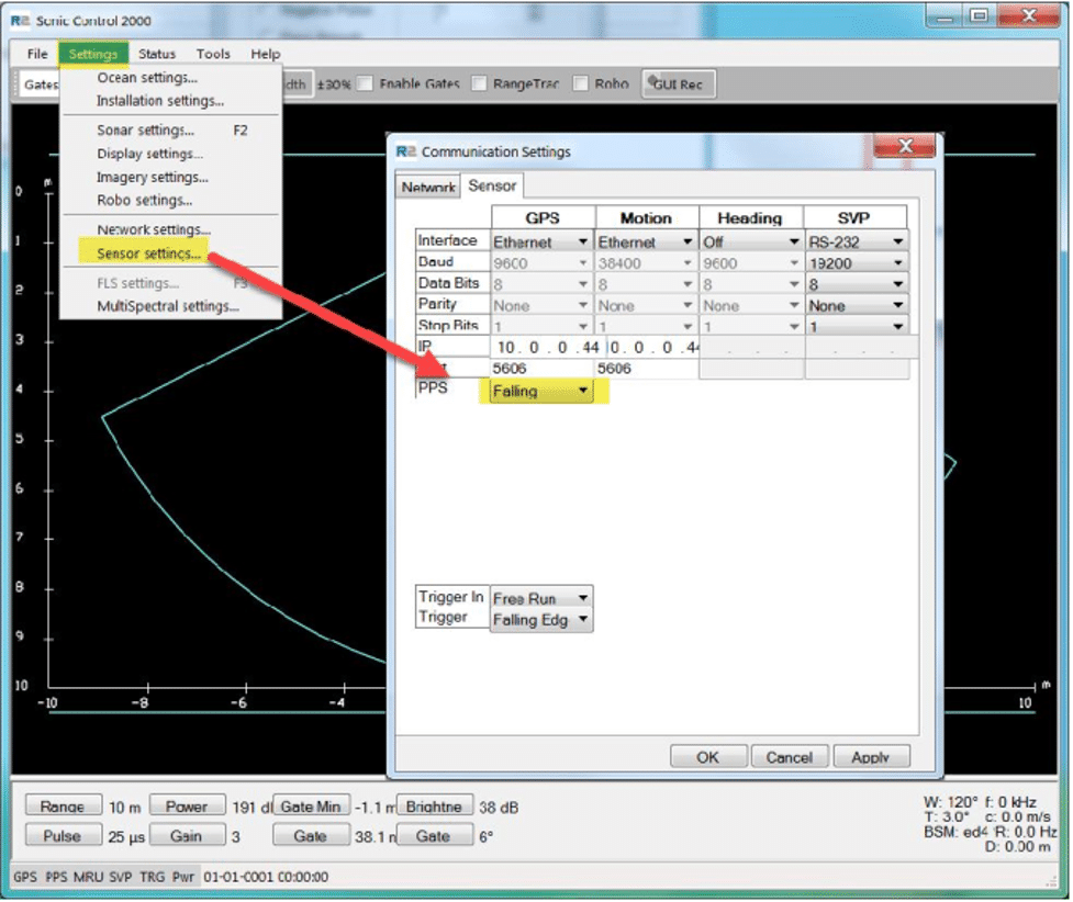
- Set the pulse width to 1 millisecond at + or – 5 volts, with a gap of 1 second. Ensure the PPS Edge Setting in Sonic Control is “Rising” for a Positive PPS Pulse or “Falling” for a Negative PPS Pulse
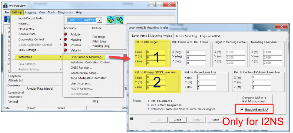
Lever Arms & Mounting Angles
- Here, we consider the center of gravity equivalent to the center of rotation. i.e. Centre of Gravity (CoG) ≡ Centre of Rotation (CoR)
- Use of the CoR is critical for obtaining correct lever arm and mounting angles
- Make your CoR = Reference Point
- Note that all POS MV lever arms should be measured from the CoR that is Designated as The Reference Point. This is despite the POS manual statement: “The reference point is defined as any convenient location on the survey vessel”
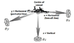
- Important: The CoR is located at the intersection of Fore-Aft / Port-Stbd / Up-Down axes. (Fore-Aft: Longitudinal Centre Line. Up-Down: Waterline. Port-Starboard: Normally ½ to ⅔ distance from transom to peak.)
Mounting measurements
For the easiest and most trouble-free mounting, only 3 measurements are needed (with Reference Point as the CoR).
- Reference Point to IMU Target (POS View)
- Reference Point to Primary GNSS Antenna (POS View)
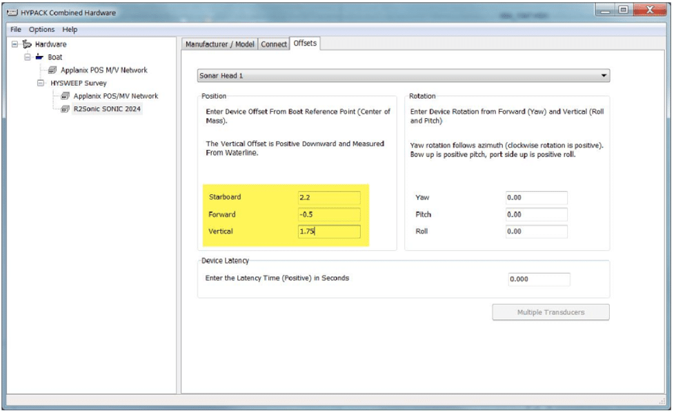
- Reference Point to Sonar Acoustic Centre (Survey Software)
- The POS MV uses a right-hand Cartesian coordinate system, meaning:
- +X=to Bow
- +Y=to Starboard
- +Z=Down
- When using DGPS, lever arms should be measured to ±0.05m
- When using RTK or POSPac MMS IAPPK, lever arms should be measured to ± 0.005m
IMU Angular measurements, relative to the Vessel Reference Frame, should not be ignored. These angles are best measured by Total Station or LIDAR unit.
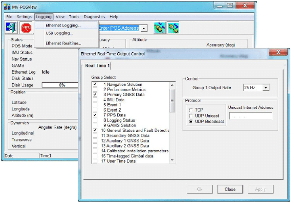
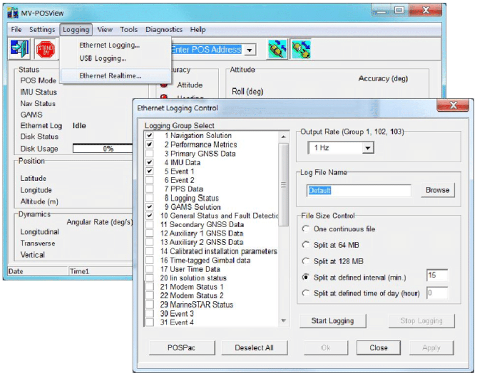
Ethernet output – real time
- Use groups: 1,3,7,10,20,102,104,111, & 113
- With HYPACK®: TCP 25 Hz
- With QINSy®: TCP 50 Hz
- Click on “POSPac”. Select 1Hz for Output Rate of Groups 1, 102 & 104
- It is recommended to save the Log File to subdirectory within survey project
- 15-minute is the time interval recommended as corrupted files (due to PC crash, power loss etc.). This means that only 15 minutes of data would be lost
Even small setup errors can make a significant difference to survey results. If you are experiencing data artefacts or other errors, it is worthwhile to go back and thoroughly check your setup, measurements and calibrations, which will help ensure trouble-free surveys going forward.